Investigating the Effect of Beams and Columns Dimension on the Floor Displacement
Alireza Heysami1 * , Navid Siah Polo2 and Milad Taghi Pour1
1
Jahad Daneshgahi Khuzestan University,
Ahwaz,
Iran
2
Faculty member of Civil Engineering Department,
Jahad Daneshgahi Khuzestan University,
Ahwaz,
Iran
http://dx.doi.org/10.12944/CWE.10.Special-Issue1.103
In this study, displacement obtained by elastic analysis of structure, with concentration factor has become a nonlinear displacement. Also, its amount shall not exceed from the specified limit in design code. Otherwise, by increasing the dimensions of beams, columns or both, the investigation of their effect on reducing displacement has been conducted(Jorge Ruiz et al.,2003). By comparing reduced displacement caused by dimension changing of beams and columns, the optimal case is determined(Jorge Ruiz et al.,2003). One of the most important results in high-rise structures and different number of opening, in both steel and concrete structure, by increasing beam dimensions, lateral displacement of floors is reduced. Also, moody period in steel structures relative to concrete, will be further reduced by increasing sections of columns and beams.
Copy the following to cite this article:
Heysami A, Polo N. S, Pour M. T. Investigating the Effect of Beams and Columns Dimension on the Floor Displacement. Special Issue of Curr World Environ 2015;10(Special Issue May 2015). DOI:http://dx.doi.org/10.12944/CWE.10.Special-Issue1.103
Copy the following to cite this URL:
Heysami A, Polo N. S, Pour M. T. Investigating the Effect of Beams and Columns Dimension on the Floor Displacement. Special Issue of Curr World Environ 2015;10(Special Issue May 2015). Available from: http://www.cwejournal.org/?p=10286
Download article (pdf)
Citation Manager
Publish History
Introduction
In recent years, attitude to displacement rather than forces is considered to investigating the earthquake effects in structures. Although still many regulation of building design against earthquake tend to use force to analyze the seismic effects on structures. In general, the four criteria of design regulations can be presented as follows:
1)Resistance criteria, by considering this criteria, each structure member should have essential strength to load share which is reached to it. So, the amount of for each member should be lower than 1(M.Ali, M,2007).
2)Hardness measure, if structure does not have essential hardness against loads, it will be suffered by a large displacement, and it make the structure vulnerable against some phenomenon, and we will discuss them in the following.6 Therefore, it is necessary to control lateral displacement in structure to avoid creating large displacements (especially the members of vertical load).
3)stability measure, issues related to buckling of structural elements and secondary effects which are created due to the performance of gravity load on displaced structure and they are known as P-∆ and they are factors that may cause collapse of stability as a secondary manner(Moon ,K.S,2010)
4)according to performance level which is considered for structure, deformation measure is introduced, structure should has sufficient deformation to reach desired performance level.9 As it can be seen in second measure, of the structure does not have enough hardness, it will has a large displacement. We can search the causes of this displacements in the following cases:
A)limiting the applied damage on structure components by entering the structure to the field of inelastic performance, actually by increasing a small amount of energy, lateral displacement will sharply increase. In other word, despite of nonlinearity of structure behavior, lateral displacement are considered as the most important factor of damage(Reza Rahgozar et al.,2010). So regulations are intended to limit lateral displacement and reduce mentioned damage.
B)limiting the applied damage on non-structural components and creation of lateral displacements, very high forces such as shear force is entered to non-structural members such as between frames. And minimizing the lateral displacement reduces these forces and damages caused by it(Reza Rahgozar et al.,2010). Since most of conventional designs are done by linear analysis, estimating the deformation amount and actual structure displacement (as a result of non-linear analyzing) by finding a coefficient to convert displacement of linear analysis to actual displacement.The proposed coefficient of third edition of regulation 2800 is considered to convert the displacements obtained from linear analysis to non-linear is 0.7R. and R is the coefficient of structural behavior. In this paper, by modeling two types of concrete and steel structure, we investigate the amount of effectively of displacement reduction by increasing dimensions of each beam and columns to investigate that if the effect of beam on displacement reduction is more or column. (.M.J. Spence et al.,2011)
The Rules of Regulation
it is stated that in determining relative lateral displacement of floor, it is required to consider displacement in the center of floor mass. In other word, relative displacement of each floor is total displacement of mass center of that floor to displacement of all mas center of its lower floor. In this edition, it is stated that relative lateral displacement of actual design or relative lateral and inelastic displacement of project, in each floor is a displacement that by considering the actual structure behavior, non linear behavior is obtained in its analysis(X. L. Lu et al.,2011) .In cases that structure analysis is done by its linearity assumption, this displacement can be obtained from following equation(X. L. Lu et al.,2011)
∆M = 0.7 ∆W (1)
Where ∆M is relative lateral actual displacement of design in floor, ∆W is relative lateral displacement of design in floor and R is the coefficient of structure behavior.
Allowed limits to relative displacement of floors (drift) are as follows:
Table 1: Allowed limits of relative lateral displacement of floors[17]
|
The maximum allowed amount of drift |
Experimental period of structure |
|
o.25h |
0.7> |
|
0.25h |
0.7≤ |
Case Study
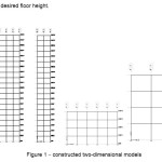
Modeled two dimensional is as shown in Figure 1.
 |
|
In this study, two types of model 20 and 4 floors, 2 and 5 opening for each of concrete and steel structures are modeled which can be assumed all of them in flexural frame. In concrete structures, elements are used in which their stress ration is between 0.8 to 1. Also, in concrete structures, beams and columns are considered with the following conditions of modeling:
Table 2: The conditions of modeled columns and beams of concrete structure[17]
|
column |
beam |
|
3%≤p≤1% |
2.5%≤p≤ 1% |
Structures in this paper are modeled as two-dimensional models. The height if floors is considered 4 meter and the width of opening is 5 m. according to the possibility of choosing seismic different conditions for models, seismic conditions for Tehran with a high width of seismic risk, soil type is considered IV and type of structure is residential. Also, the applied load on structure is assumed 3250 Kg per meter died load and 1250 kg per meter live load. for linear analysis of structures, ETABS Ver:9.7.0 software is used.
Modeling
First, each of the concrete and steel structures of 20-storey and 5-storey are analyzed. The displacement type is exclusively considered for that type of structure. Then once by increasing beam section and other time by increasing column and finally by increasing both of them , the results are compared with each other. In this paper, we investigated the results of displacement, reversal anchor, the total weight of structure skeleton, and moody period of each of these elements. At the end, the effect of each of these elements is determined to reduce the displacement. After comparing displacement and other parameters in each of the concrete and steel structures, another time this investigation is conducted between concrete and steel structures in similar floors. In the end, the amount of effectiveness of changing beam and column dimensions between structure types are also discussed. Method in this study is that by displacing obtained from structure linear analysis by ETABS software, and substituting in equation 1, inelastic actual displacement is obtained. Then by mapping displacement curve- height is each of increasing beam cases and column and both, we will discussed the results.
Also, for convenience, maximum displacement of models is limited to maximum allowed amount in table 1.
Investigating Results
First, we will investigate the obtained results of increasing amount of beam and column dimensions on displacement. Then, other parameters such as reversal anchor, moody period increase skeleton weight of structure are considered due to dimension increasing of beams and columns.
 |
|
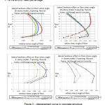
AS shown above, in model 20-storey and 5 opening, by increasing beam dimensions, displacement will increase. Also, by increasing column dimensions, displacement is also increased. Another important point us that by increasing dimensions of beams and columns, floor’s displacement will not have a significant change relative to beam dimension increasing. Therefore, it is better that to reduce DRIFT of floor, only increase the beam dimensions. In model 20-storey and 2 opening, as previous model, by increasing beam dimensions, displacement will reduced and the effect of increasing beam dimensions relative to columns is more to reduce the floor displacement. Also, in that model, by combined increasing of beam and column dimensions, DRIFT changes is not much different relative to beam dimensions. In the model 4 –storey and 5 opening, only by increasing the dimensions of beam and column section, simultaneously displacement has been decreased. Increasing columns and beam dimensions did not cause a significant change in floor deformation. In model 4-steory 2 opening, unlike other models, by increasing column sizes, displacement amounts of floor has been significantly decreased. Also, by increasing beam dimension or both of them (beam and column) simultaneously, it dose not have a considerable effect in floor displacement. According to results from figure 2 we can conclude that in most cases except in model 4 floor and 2 opening, that it can be considered as a structure component with low height and low opening, by increasing beam dimensions, floor displacement will be reduced considerably.
In the following picture, concrete structure is placed in different cases of increasing beam and column dimensions in constructed models:
 |
|
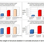
According to figure 3, for structures with 20 stories, by increasing beam dimension in DRIFT reduction of floor, Skeleton weight had a significant reduction relative to other cases. Therefore, by this method (increasing beam dimensions), we can reduce the amount of floor displacement to an acceptable amount. But in model 4 stories and 5 openings has the most displacement reduction by increasing combined beam and column dimensions obtained of figure 2. The weight of Skeleton is greatly increased and it is not economically optimal. Also, it is observed in 2 opening model, by increasing column size which causes to reduce floor displacement, skeleton weight is increased and is not affordable. So it seems that in structures with low height, since DRIFT wont have a significant increase, it would better to don’t increase the sections dimensions.
 |
|
According to figure 4, reversal anchor does not have a considerable change.
This means that reversal anchor is not dependent to changing the section dimensions. Thus, depending on available sections in structures, their results of analysis will be identical.
 |
|
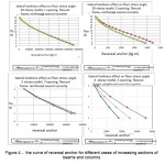
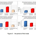
According to the analysis results in figure 5, for structures with 20 floors, by increasing the sections of beam dimensions which causes reduction of displacement, Moody period is dropped.
This case is appropriate for near-fault earthquakes that one of its characteristic is high ratio of period. Also in model 4 floor and 5 openings in which floor displacement is reduced by increasing beam and column dimensions, period has decreased significantly. In 2 opening model, by increasing section dimensions of columns, period time is reduced and it is appropriate. As it was mentioned before, in this model ( 4 floor, 2 opening), by increasing column dimensions, structure weight has been increased and it will not be affordable.
 |
|
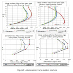
According to figure 6, in steel structures unlike concrete beams, without exception in all models, by increasing beam dimensions, displacement changes are reduced. Also, by increasing the dimensions of beams and columns, DRIFT of floors has declined considerably. So, we can investigate these results with other results, and it if it is favorable, and by increasing section dimensions, we can reduce floor displacement.
Weight of structure skeleton will be as follows in different models
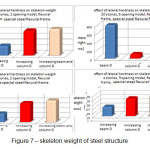 |
Figure 7: Skeleton weight of steel structure Click here to View figure |
According to the results, in a structure with 20 floors and 5 opening, by increasing the number of beams in reducing floors lateral displacement, structure weight is increased greatly. So in high structures with a number of openings, increasing section to reduce DRIFT of floors is nit cost effective. But, in other models, such as a structure with 20 floors and 2 opening and two 4 floor models, by increasing the number of beam section, the weight if structure is not changed and it is cost effective, in this regard. It should be noted that by decreasing structure weight, structure will be in good condition in term of seismic performance. And lower balance power will be applied to it.
 |
|
According to above results, in steel structures such as concrete structures of reversal anchor curve is similar for increasing beam sections and columns and it is not associated with section increasing. So, it seems that, generally reversal anchor is obtained based on arrangements of beams and column section. And by increasing the number of beam sections of beams or columns, it will not change.
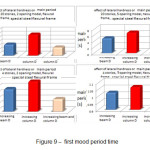 |
|
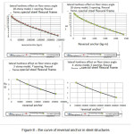
According to figure 9, against with concrete structures with increasing beam section, moody period time is decreased for all models. Therefore, it will be so appropriate in term of near-fault earthquake. And in the situation of increasing beam and columns together, In addition to significant reduction in floor lateral displacement, moody period time will be less relative to increasing beam sections. Therefore, in term of seismic performance, it is better in near-fault earthquakes.
Conclusions
*in high-rise structures and different number of openings, in both steel and concrete by increasing beam dimension, lateral displacement of floors is reduced.
*in steel structures, combined increasing of beam and column increasing, relative to concrete structure will reduce DRIFT .
*moody period in steel structures relative to concrete, due to combined increase of beam and column sections, it will be further reduced.
Structures with low height, in concrete structure with an increase of beam and column and in steel type, only by increasing beams, lateral displacement of floors will be reduced. It should be noted that in steel structures, in a situation of increasing beams and columns, we will have a better performance in DRIFT reduction.
*moody period in low height structures also for concrete structures will be more by increasing beam section relative to combined increasing beam and column. So, to reducing floor displacement, it is better, to increase section, simultaneously.
*structure weight will be reduced for models with large height in concrete strictures by reducing DRIFT caused by increasing beam dimensions. While, in steel structure except in a case of many opening, this will be true.
*in low-height structure, structural weight will be minimal for two types of concrete and steel structures, only by increasing the beam dimensions in DRIFT reduction.
*reversal anchor will not change for all structures with different opening numbers in two types of steel and concrete structures, by increasing the dimensions of beam and columns.
References
- Cherry S, Filiatrault A. "Seismic response control of buildings using friction dampers". Earthquake Spectra; 9(3):447–66(1993).
- Yu-Yuan lin and Eduardo Miranda, “Evaluation of equivalent linear methods for estimating target displacements of existing structures,” Eng Struct 48,pp 1121-1133(2009).
- Jorge Ruiz-Garcia and Eduardo Miranda, “Probabilistic estimation of residual drift demands for seismic assessment of multi-story framed buildings,” Eng Struct 45,pp 1151-116(2008).
- Bungle S.taranath,PH.D,P.E,SE “Rienforced concrete design of tall building “,(2010)
- M.Ali, M., and Moon ,K.S.,”Structural Developments in tall buildings:Current trends and future prospects”school of architecture,university of llinois at urbanaâ€champaign,champaign,IL 61820,USA,(June 2007)
- M Halis Gunel H Emre ilgin “ A Proposal for the classification of structural systems of tall buildings “ Faculty of Architecture, Middle East Technical university ,Ankara 06531, (2007).
- Moon ,K.S “Stiffnessâ€based design methodology for steel braced tube structures : A sustainable approach “,(2010).
- Moon,K.S.,”Dynamic Interrelationship Between Technology and Architecture in Tall Buildings” , Thesis (PHD) Massachusetts Institute of Technology,(June 2005).
- Moon K S ”Materialâ€saving Design strategies for tall building structures” school of Architecture ,university of Illinois at Urbanaâ€champagin,champagin,IL61820,USA,(2005).
- Kheiroddin,A. and Zahiriâ€Hashemi,R. “Investigation of the shear lag behavior in braced tubular structures”,CSCE2008,Annual Conference,June10â€13,(2008).
- ASCE ,”Minimum Design Loads for buildings and other structures “ American society of civil engineers(1996).
- Reza Rahgozar Ali Reza Ahmadi Yasser Sharifi ” A simple mathematical model for approximate analysis of tall buildings” Applied Mathematical Modelling 34 2437–2451(2010).
- Reza Kamgar , Mohammad Mehdi Saadatpour ,” A simple mathematical model for free vibration analysis of combined system consisting of framed tube, shear core, belt truss and outrigger system with geometrical discontinuities”sApplied Mathematical Modelling ,(2011) .
- S.M.J. Spence , M.Gioffre ,” Efficient algorithms for the reliability optimization of tall buildings ” J Wind Eng Ind Aerodyn 99 ,691–699(2011).
- Mohsen Malekinejad, Reza Rahgozar, “A simple analytic method for computing the natural frequencies and mode shapes of tall buildings”, Applied Mathematical Modelling 36, 3419–3432(2012).
- X. L. Lu, H. J. Jiang,” Research and Practice of Response Control for Tall Buildings in Mainland China” , Procedia Engineering 14 ,73–8( 2011).
- Mir M. Ali† and Kyoung Sun Moon, ” Structural Developments in Tall Buildings: Current Trends and Future Prospects”, Architectural Science Review Volume 50.3, pp 205â€223(2010).